I want to thank Bee Mama for giving me the opportunity to write this post (and having the patience to put up with my silliness to begin with). Her posts are usually well- written discourses on gardening philosophy or wildlife, punctuated with pretty pictures. This post is an exception: this post is about my adventures in designing and building an inexpensive honey extractor. If you’re not interested, you’re welcome to skip it. Bee Mama promises another garden-related post soon to clear this one from the top.
This post is a long, complicated description of building a technical piece of bee keeping hardware. It is not intended for the general audience of this blog, but as a resource for other home/backyard beekeepers. Please bear with any awkward descriptions, and appreciate that the thing actually works, even with my hack carpentry. If I can make this work, you can. At the end of reading and if you have questions or comments, or if you decide to build one of your own and have questions or suggestions, please email me at: AustinBeeDaddy@gmail.com
Introduction
We keep bees and bees make honey. Lots of honey. A full honey box can contain over 3 gallons of honey. While we don’t manage the hives to produce honey, we do end up taking honey frames out to give the bees more room to continue their honey hoarding behaviors. They can’t change who they are, so we have to adjust our keeping them. For example, we recently took out 10 frames (about 80% full of honey) and installed 10 empty frames so that the bees would have more room…to store the spring flush of honey-making.
Originally, we just crushed and strained the comb. We’d get all the honey out at the cost of destroying the comb, wasting a lot of bee effort and energy. Later we purchased an extractor. An extractor spins out most of the honey while retaining the wax. The comb can be reused and the bees don’t have to rebuild from scratch. The extractor worked excellently for a year, before breaking. Not wanting to reinvest in another not-too-pricey, but clearly not great piece of equipment (that lasted only a year), we tried other extraction methods. These experiments at best extracted 50% of the honey. That’s a lot of honey to leave in the frame.
Not satisfied, I surfed the web for honey extractor plans. No plans I found looked feasible. In the end, I combined some things I found and my own experience and designed my own extractor. It worked excellently on the initial run, successfully extracting over 2 1/2 gallons of honey from the 10 frames we’d pulled.
The design goes together well. The pieces are readily bought or easily built and the extractor breaks down into to small, easy-to-clean-and-store pieces. Being self-made, if a piece breaks, it is simple and inexpensive to replace.
I am copyrighting these plans. I don’t want to profit from this design but have no problem benefiting charities. To be licensed to use this plan, please make a donation to $18 dollars to a charity of your choice and $18 to either of these funds: “The Shoshana Ruth Weintraub Fund for Jewish Youth Programming” or “The Shoshana Ruth Weintraub Fund for The Science Magnet Middle School Band Youth Programming” c/o The Austin Community Foundation, P.O. Box 5159, Austin, TX 78763 or via their website https://austincf.fcsuite.com/erp/donate/list
I should add several caveats to what you’ll read and see. From my original idea, I redesigned as needed. I also was not good at taking pictures for every step of the building process. Therefore, some pictures used to demonstrate construction come from different iterations of the design, using different wood widths. Also, some of the shots are staged; I would never do honey work without bunches of towels to catch the sticky stuff and definitely not on a nice wood floor. Please don’t be deceived. Finally, I am a hack carpenter; I don’t use proper technique when building and some of my equipment has seen better days.
One word of advice: I try to show pictures of everything, and the pictures precede the text describing it. Open the picture in a new browser so it is easier to go back and forth with the description
General Design and Use
The plan is simple: a rotor that holds two to four frames of honey that spins in a food safe garbage can. The cost of the parts is about $70.
There are five basic pieces to the honey extractor:
- A container (a food safe plastic garbage pail
- The base
- The rotor
- The top
- The engine (a variable speed drill)
The following is a description of how the extractor works (how to build it follows).
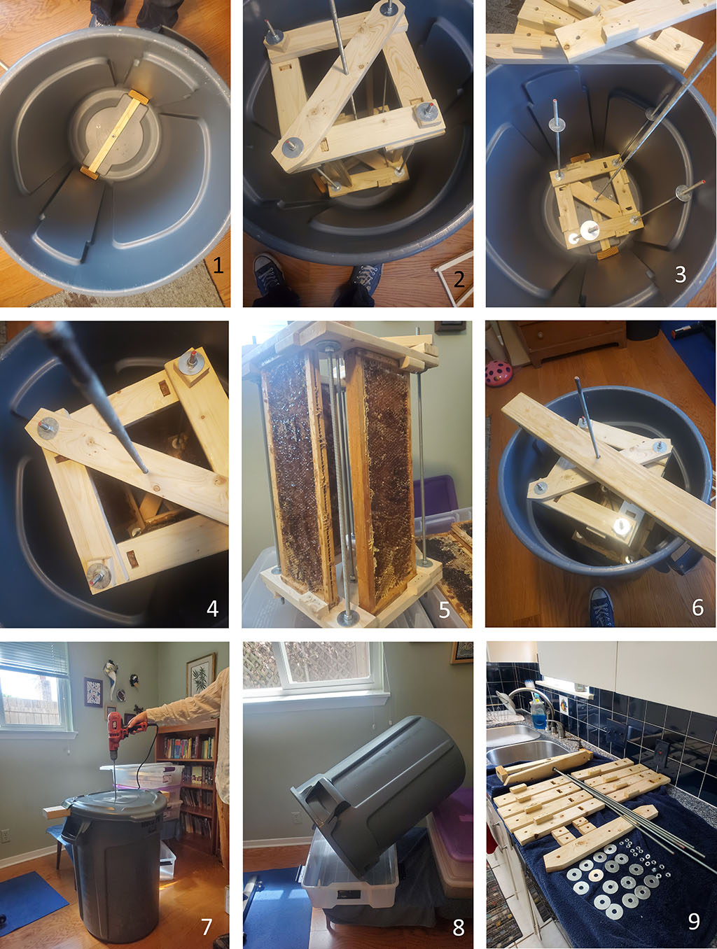
Take the base and place it into the container (figure 1-1). Then take the rotor and put it in the container so the axle fits into the base (figure 1-2). Remove the top pieces of the rotor (figure 1-3) and fit in four honey frame and so the frame top fits into the hole in the bottom holder and the frames sit tight to the external bumper (figures 1-4 and to make it clearer – I removed the rotor from the container in figure 1-5). Replace the top rotor pieces and put on the top cross member (figure 1-6). You now place the lid on the extractor (optional); the lid prevents honey splattering out, but even without the lid, the honey doesn’t splatter out. Much.
Now using a drill – spin the rotor for about 20 to 30 seconds (figure 1-7). The outsides of the honey frames have now been processed, now you need to get the insides of the honey frames. Remove the top member and the top rotor pieces, flip the frames so the insides are now directed toward the outside of the can, replace the rotor top and top pieces and spin again. Once those four frames are processed on both sides, remove the top member and the top of the rotor, remove the frames and insert the next four frames. Note: Balance is important; make sure that if you don’t have four full frames to process, use already processed frames in the other holders to balance the weight.
After all the honey has been spun from the frames, I found that tilting the receptacle and pouring it into a large plastic (food safe) packing box (figure 1-8), works. Leave it for a day and then use a spatula to get the last gooey remnants. This allows me to transfer the honey to the kitchen easily and start processing it through sieves and bottling in with very little lost. I originally was going to install a honey gate, but since I would still have to do the tilt method to get out the last bit, it was easier (and probably less sticky) to not have a honey gate. Once finished, I then take apart everything (down to the nuts except the bottom axle assembly held by lock nuts), put everything out for the bees to clean up and bring it in in the evening. We then wash everything in the sink (figure 1-9), except for the can, which we wash in a bathtub.
Building the Extractor
To Build this you need:
| Count | Part | Comment |
| 1 | Garbage Can | Make sure it is labeled as food safe plastic |
| 3 | 1″x4″ 8′ pine | |
| 1 | 1″x2″ 8′ pine | |
| 4 | 2 foot 5/16” threaded rods | |
| 2 | 3 foot 5/16” threaded rods | |
| 16 | common nuts | Should have 4-6 more handy – you’ll drop one or two along the way in the honey |
| 16 | fender washers | Should have 4-6 more, see above |
| 4 | lock nuts | |
| 4 | tee nuts | I could only find these in boxes of 20 |
| 1 | hub | |
| 4 | 3” 5/16” carriage bolts | Not necessary for the final extractor, but useful in construction |
| 1 | Large storage container | Make sure it is food safe. Not necessary for the extraction, but it’s a good transfer from the extractor to processing |
When I say food safe plastic, you should know all food safe plastic is rated and stamped on the product ‘NSF’. Look for this stamp to see if the plastic pieces are food safe:

The cost of the parts is about $70 (maybe a bit more – I had a lot of the hardware already in my garage). The most expensive piece is the food safe trash can.
There are three pieces to construct: the base, the rotor and the top. The base and top piece are easy to build. The rotor is more complex. Study this picture to see how it is built and the terms I came up to describe the parts:

The rotor has a central axle that is a 3-foot threaded rod. Around the rod, the honey frames are held by frame ‘holders’ on top and bottom. The holders have a hole to hold the frame top in place (in this picture there is a top bar of a honey frame in the hole), and a bumper to prevent the frame from spinning out due to centrifugal force. The holders are held together by four 2-foot threaded rods. Two diagonals (one on top and one on bottom) help hold the holders squarely and the bottom diagonal is ’permanently’ fitted to the axle to provide spin. The only other part is four spacers on the outside corners without diagonals where the rod connects the holders together (to allow an equal distancing).
This design builds two different sizes of rotors. The one pictured above I call the square rotor. It is for a standard 6 1/4” honey frame (also a 5 3/8” honey frames). It has 4 holders of 12” to allow the processing of four frames at once. The other rotor, I call the rectangular rotor, is for the 9 1/8“ brood frames. It is a rectangle made up of 2 15” holders (which will hold the actual frames), and 2 8” holders. This allows processing for two brood frames at a time.
Building the rotor
Cutting the Holders
The frame holders (or simply holders) sit on the top and bottom of the honey frame and hold it in place while the rotor spins.

Take the three 1”x4” lumber pieces and rip them to 2 1/2” wide on a table saw. Be sure to keep the kerf of the saw blade outside the 2 1/2” inches. You will use both the 2 1/2“ pieces and the 3/4” pieces of the wood. Take the 2 1/2” cuts and cut them into (figure 4-1):
| 4 | 8 inch long pieces | |
| 8 | 12 inch long pieces | |
| 4 | 15 inch long pieces | |
| 4 | 18 inch long pieces |
Now take one piece of each size. Mark a top and bottom square on each end (easiest way is taking another piece and laying it over, figure 4-2) and mark the center (easiest way is the find the diagonals of the square, figure 4-3, figure 4-4). Drill a 5/16” hole in the pieces in the centers. Once you have drilled those holes, use the piece as a model to drill all the other pieces of the same size. Exactness in the dimension of the pieces is less important than having the exact distance between holes. After drilling both holes the first piece and drilling one hole in the other pieces, insert a carriage bolt to hold the several of the pieces together (with the first piece on top), and then drill the second hole using the top piece as a guide (figure 4-5). Your final lumber should look like figure 4-6.
Cutting the Diagonals

You will be cutting 4 diagonals, two for the square rotor and two for the rectangular rotor. We’ll start with the rectangular holders. Lay out a rectangle consisting of 2 15” holders and 2 8” holders, using carriage bolts (figure 5-1). Measure the diagonals to make sure they are the same length, and the rectangle is ‘square’ (figure 5-2). Lay one of the 18” wood pieces you cut earlier diagonally across the rectangle and mark the place for the bolt holes (figure 5-3). Drill these holes out with a 5/16” drill and then find the center of the holes and drill a center hole (figure 5-4). Peg the diagonal on the bottom of the rectangle and mark the corner (figure 5-5). Cut off the diagonal to be square with the edge. Using the diagonal, you just finished, use it as a model for an exact matching diagonal. Use the diagonal you just finished as a guide, make a second diagonal of exactly the same dimension. Precise matching of the holes in the diagonals is more important than exactness in size (figure 5-6).
Repeat the process above to make 2 diagonals for a square rotor, substituting four 12” holders for the two 15” and 2 8” holders.
Finishing the Holders – Cutting Frame Holes and Adding Bumpers

You have cut the general holder, but now we need to add some important additions. Look at figure 6-1 to see how the finished frame holder looks. Notice the rectangular hole, which the top bar of the honey frame fits into, and the bumper which sits on the outside edge of the holder to prevent the frame from spinning out. Figure 6-2 shows a frame fitting into a holder.
First, we’ll make the hole. Take a 12” holder and an outside piece of a 6¼” honey frame. Center the frame between sides and the overlap lines and trace the top of the frame (figure 6-3). Now draw a rectangle around this tracing (figure 6-4). Then take a top bar and center the outer notch over the rectangle and mark the sides (figure 6-5), this area (figure 6-6) is the hole you will cut out. Repeat the same with the other seven 12” holders. Take the four 15” holders and a 9 1/8” frame side and do the same with them (the 8” holders will remain untouched). For these 16 pieces, drill a hole in the cutout area and insert a jigsaw and cut out the hole (figure 6-7). After removing the holder from the jigsaw, fit a frame into the hole and see if it fits (figure 6-8). The frame should fit snugly but not tightly.
Now we make the bumpers. Take the long thin piece left over from the ripping of the 1”x4”s and chop it into 1 1/4” pieces. Fit a frame into each of the holders and draw a line along the bottom edge (figure 6-9, The piece has been moved to show the line). Now nail the bumper along the outside edge (figure 6-10). Because of the thinness of the wood, drill pilot holes first. Do this with the other 11 holders. The frame should fit well on the holder (figure 6-11). Notice that half the holders have bumpers on the left and half have bumpers on the right (figure 6-12). This is because the bumpers are on the outside of the rotor holding the frame in. The holders used on top of the rotor and the ones used on the bottom are mirror reflections.
Cut four 2 1/2” squares from original wood and drill a hole in the center to use as spacers (figure 6-13)
Building the Axle
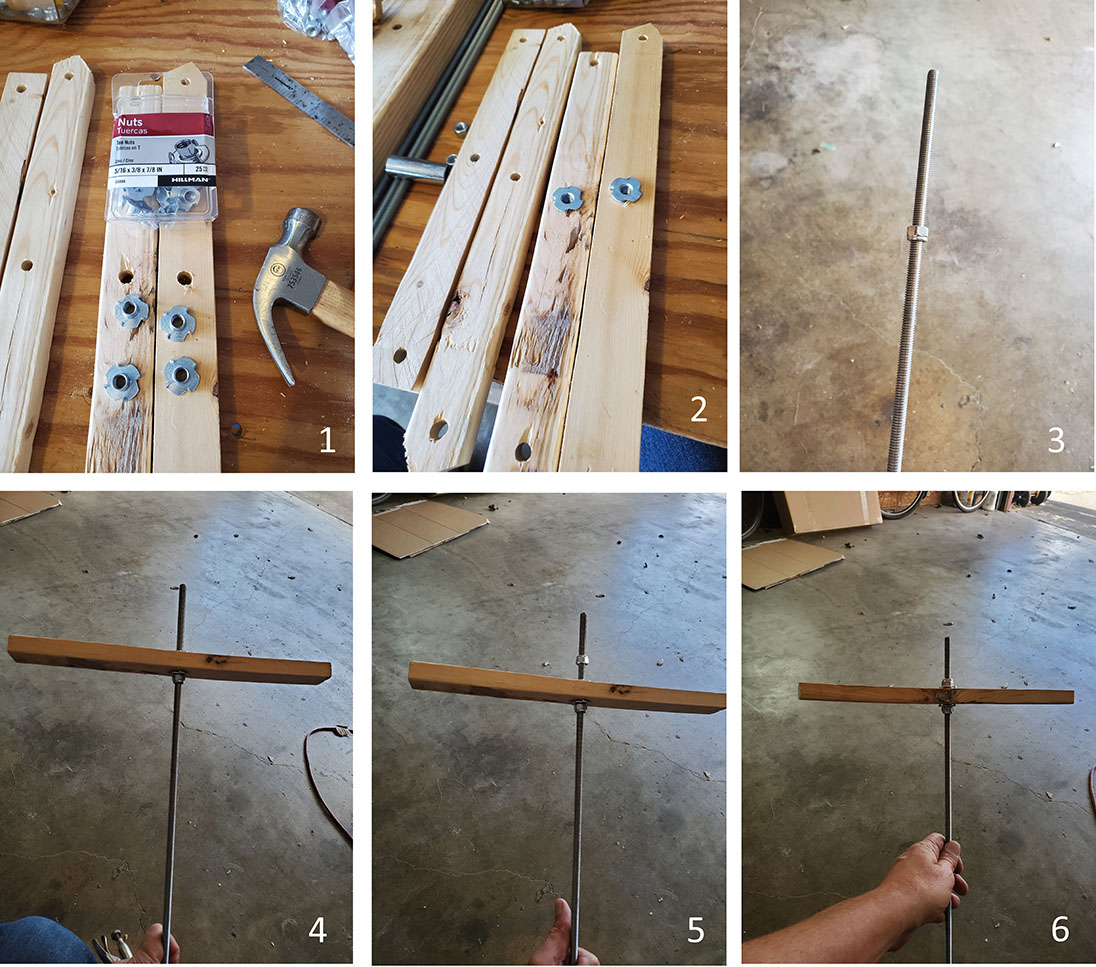
Most parts of the rotor come apart for cleaning and storage. The Axle assembly is an exception. The bottom diagonal is strongly connected to the rod to it can turn the whole assembly without slipping. This is done with lock nuts and tee nuts. For those not familiar with tee nuts, they are nuts with spike flanges to dig into the wood (figure 7-1). Take a diagonal for the 8”x15” rectangle and a diagonal for the 12”x12″ square and hammer two tee nuts into either side of the center hole (figure 7-2). Take the 3’ threaded rod and thread a lock nut about 8 inches down with the flat side up (figure 7-3). Take the diagonal and thread it down to the lock nut (figure 7-4). Take another lock nut and thread it on the rod (flat side towards the wood) until the nut is just on the rod and then thread the lock nut exactly 35 rotations (make sure the rod does not turn. figure 7-5). Now thread the diagonal and the initial lock nut up the rod until it meets the new lock nut (figure 7-6).
Building the Rotor

Now that you have completed the holders and the axle, it is time to assemble them into the rotor. We’ll build the square rotor (since this the rotor I needed for the 6¼” frames I was processing that day). The first step is to take the four, 2’ rods and put a nut and a washer about 8 inches down from one end (figure 8-1). Separate four, 12” holders, making sure the holders you grab all have the bumper on the left side. Place two of the 12” holders horizontally on the rods with the top frame holes in opposite directions and the bumpers on the outside and on the side of the wood facing the long side of the rods (figure 8-2). Take two other 12” holders and place them vertically on the rods completing the square. Make sure the frame holes are in separate corners of the square and the bumpers are all on the outside edge of the square and on the long rod side (figures 8-3 and 8-4). Take the axle assembly and place it diagonally on the square (figures 8-5 and 8-6). Place 2 spacers on the two rods not used by the axle (figure 8-7). Take four washers and place them on the four rods, then take four nuts and place them on the rods until the nut top is even with the top of the rod (figure 8-8). Tighten all four nuts precisely 15 rotations (make sure the rod doesn’t move), adjust the wood pieces to meet this new nut and washer and tighten the other nut to the assembly (figure 8-9). You just created the bottom of the rotor.
Flip the rotor up and take four top bars and put them in the frame holes, take four nuts and put them on the upper end of the rods about 10” from the top (below the cut out on the top of the top bar) and place four washers on top of the nuts (figure 8-10). Place the other 12” four holders on the rotor so they fit snugly on the frame top bars. Notice the bottom rotor square has two low holders and two higher holders. The upper holders should match this pattern, the holes in the holders should fit snugly onto the top bars and the bumpers should be down and on the outside mirroring the holders on the bottom (figures 8-11). Place the diagonal on the axle and two of the rods and spacers on the other two rods. Take a washer and a nut and tighten both the nuts on each rod for the upper rotor (make sure the rod doesn’t turn when tightening – this could spoil the precise distancing used in the bottom of the rotor) (figures 8-12 and 8-13).
Building the Bottom Piece

Take a deep breath, the hardest part of this is over. The rotor is the heart of the extractor. It is held in the receptacle by a bottom and a top piece, both of which are relatively easy to construct. We’ll start with the bottom piece.
Notice that the bottom of the trash can has two slots (figure 9-1). We’re going to use those two slots to hold the bottom in place. Turn the can over and notice the underside for of two slots. Take a 4” piece of 2”x4” and center it over the slot. Mark where the edge of the slot comes to the 2”x4” (figure 9-2 – notice the wood is flipped over showing the line). Cut the 2×4 along that line and fit it into the slots inside the can. Take a 1”x2” piece and measure and cut it to fit between the 2×4 pieces (figure 9-3). Screw the pieces together, find the center and drill slightly into the piece and insert the hub with glue (figures 9-4 and 9-5).
Building the Top Piece

Last piece – I promise; this is the top of the mechanism.
Take a 2½ foot length of 2”x4” and center it over the top (figure 10-1). I found the can handles to be a great centering device (figure 10-2). Mark the curve of the pail on both ends of the 2×4 (figure 10-3) and then draw out a rectangle that enclosed that curve and half the depth of the 2×4 (figure 10-4). Cut out that rectangle and check the fit to the can (figure 10-5). Fit the lid tightly to the can and with a utility knife, cut flaps to allow the 2×4’s to extend out (figure 10-6). Drill a 5/16” hole through the center of the lid and through the 2”x4” (figure 10-7). Next, take this all apart. Put the bottom piece in the can, fit the rotor axle into the bottom and put the 2×4 on the can (figure 10-8). You’ll notice the rotor cannot spin freely as the rods will hit the top 2”x4”. Mark where the rotor hits the 2”x4 (figure 10-9). You’ll want to do this on both sides and both ends of the 2”x4” (figure 10-10). This is where the square rotor will hit the top piece, the rectangular rotor will hit it in a different location. Remove the top piece and the rotor. Disassemble the rotor and build the rectangular it with the 15” and 8” holders. Place it in the can and mark where it hits the 2×4 (figure 10-11). Add about ½” to 1”to the outside marking and cut out these rectangles halfway through the wood (figure 10-12, 10-13). Reassemble the whole mechanism (in can, base, rotor and top) and make sure the rotor spins completely and freely. Take apart the 15” rectangular rotor and rebuild the 12” square rotor, Reassemble the whole mechanism and make sure this rotor spins cleanly.
Ta-da! – You are Done!
You have an extractor. Take the extractor apart, sand it down cleanly, and tack well. We washed everything twice, in hot water, and thoroughly. We store ours in a closet, all parts fitting neatly in the can, except for a bit of the axle piece which pokes out about 5 inches.
If you have questions, contact me at: AustinBeeDaddy@gmail.com